

How To Fix Micro Usb Charger Cable
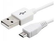
If y'all are searching for the USB wiring diagram, you are at the right place. The wiring diagram includes any combination of unlike types of USB connectors. The most mutual is "USB micro-B" to standard "USB-A" which is generally represent in mobile chargers.
USB wiring diagram comes in handy when USB port or connector either of them malfunctions or completely out of lodge, as well for engineers and hobbyist who wants to explore the electronics practically.
This malfunctioning occurs due to excessive utilize of USB wire (here excessive use ways repetitive use of wire or connecting port in a short duration of time). Improper employ like rugged applications, inappropriate inserting into port, i.e without checking port orientation.
Another practice is angle the wire greater than 90 degrees, which causes the copper wires in the bundle to get damaged due to its slightly brittle holding. Copper is having one of the best malleability and ductility backdrop. And therefore copper is widely used as a conductor in a wire even having this property, the copper wire undergoes deposition.
Before wiring USB y'all need to know the pinout diagram of USB. Below is the effigy showing the pinout diagram of the USB micro-B and USB-A wiring diagram.
Type-A USB pinout diagram, micro USB pinout diagram along with USB wiring diagram:
This cablevision is well-nigh ordinarily used in mobile charger for charging mobile phones and equally a USB data cablevision to connect mobile devices to tranfer files and images betwixt personal computers and phones.
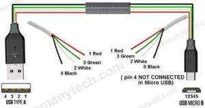

Description: USB wiring is simple but not that simple this is because on irresolute the frame of reference the pinout looks inverse. Observe the to a higher place pinout the front end is different than that of back end and thus it requires to cheque the connectivity of both ends with a digital multimeter (above micro USB pinout fabricated it uncomplicated for you).
Table of male USB-A pinout & USB-B pinout:
Pin no.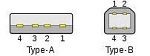 | Name | Wire code | Description | |
|---|---|---|---|---|
| 1 | VCC | Red/ Orange | +5V (dc power) | |
| ii | D- | White/ Golden | Data- (information from device to host) | |
| three | D+ | Green | Data+ (data from host to device) | |
| iv | GND | Black/ Blue | 0V (dc ground) |
The table showing pin number and their nomenclature along with its function in short.
- Pin no.1 showing the power supply (+VDD) through that pivot the ability is supplied to the device or any equipment which is also an indicator of handshake signal, means "the device is connected".
- According to the USB standard power supply is +5V.(merely note that the capacity of the power supply is different for unlike USB versions)
- Whereas, "pivot no. 2" (-D) is used as a differential data pivot, similarly "pin no. 3" (+D) is too used equally a differential data pin.
- The work of the differential information pin is to transport and receive the information in a particular format called USB protocol.
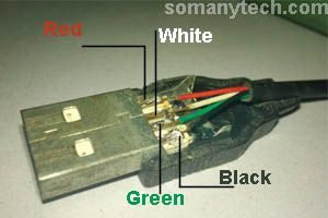
- Pivot no. iv is used as basis. The color code for the wire used in the USB cable reddish, white, green, grey, black for pin numbers 1, ii, 3, iv and 5.
- Delight take annotation of type-A & blazon-B accept the aforementioned pinout diagram after arranging on the basis of similarity of shape.
USB pinout and its connector:
There are the female connectors for each of the male connectors in applied having the same pinout as that of the male person connector. The virtually mutual types of connectors are displayed in this paradigm.
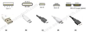
Table of mini and micro USB pinout blazon-b & type-a:
| Pin no. (look pinout figure) | Name | Wire code | Description |
|---|---|---|---|
| i | VCC | Red | +5V (dc power bus) |
| 2 | D- | White | Data- (device to host) |
| 3 | D+ | Green | Data+ (host to device) |
| 4 | ID | Due north/A (night blue / black)* | OTG-ID (mostly not connected, if so then grounded/ according to the device need) |
| 5 | GND | Black | 0V (dc footing) |
- The pinout diagram for the micro USB type-B very like to USB type-A except for the concluding ii pins 4 and five. Also, it is the same for micro USB type-a and micro USB type-b.
- The pivot no.ane is +5V acts as a source to the device or source from the device.
- Pin no.2 and pin no.3 are information lines (as well called differential information lines because its application varies with the requirements).
- The pin no. iv (ID)is used for device identification especially in modern devices for OTG connections eg. smartphone OTG connector to connect a USB drive directly to the mobile telephone.
- And the last pin no. 5 is a connection for ground indicate which is pin no. 4 type USB-A through a wire.
How to discover the USB wiring diagram easily?
Step1: Showtime of all find out the type of USB connector used in the cable.
Step2: Later on the identification of the type of USB connector used on both ends, annotation downwards the pinout diagram of that particular USB type.
Step3: Notation downwardly all the color of the cable and where it is connected to the actual USB connector on a page. (rough sketch diagram volition work)
Step4: At present connect connector pivot and wires from the ataxia according to the color code and pinout of that particular USB connector on the page using a pen, and your USB wiring diagram is ready.
Listing of standard USB connectors bachelor commercially in the market which you tin purchase:
1) USB A male to USB B male.
ii) USB A male to USB B female.
three) USB A male to mini USB B male.
4) USB A male to micro USB B male.
five) USB A male to USB C male.
vi) USB A female person to USB C male person. (USB C OTG) and many more.
Micro USB pinout insight and USB-C:
- The micro USB connector is most commonly used for charging mobile phones and various other portable devices like Bluetooth headset, Bluetooth speaker, Mini drones, Power Banks.
- Some of the device manufacturers use their ain standard of not connecting the data pin, every bit the cablevision is only made to work for charging purposes where only power charabanc/ wire is required to reduce the manufacturing cost.
You must have had idea of the question, why nearly of the devices use micro USB?
Most of the devices use micro USB due to the fact that it is meaty than all of its precedents in shape and size. And after that, no other blazon of USB is able to replace information technology except USB-C ©.
USB-C is more than circuitous micro USB-a than micro USB-b. The micro USB-C is simply called as USB-C.
The image and pinout of micro USB C are equally follows:
| Pin | Name | Pivot | Name | Description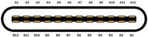 |
|---|---|---|---|---|
| A1 | GND | B12 | GND | DC footing (+0V) |
| A2 | TX1+ | B11 | TX2+ | Super speed data transmit+ (host to device) |
| A3 | TX1- | B10 | TX2- | Super speed data transmit- (device to host) |
| A4 | VDD | B9 | VDD | DC power (+5V) |
| A5 | CC1 | B8 | CC2 | Ability commitment communication line |
| A6 | D+ | B7 | D+ | speed data transmit- (host to device) |
| A7 | D- | B6 | D- | speed data transmit- (device to host) |
| A8 | SBU1 | B5 | SBU2 | secondary bus |
| A9 | VDD | B4 | VDD | DC ability (+5V) |
| A10 | RX2- | B3 | RX1- | Super speed data receive- (device to host) |
| A11 | RX2+ | B2 | RX1+ | Super speed data receive+ (host to device) |
| A12 | GND | B1 | GND | DC footing (+0V) |
- You tin see a noticeable difference between USB C and micro USB. As you lot tin observe that USB C tin be inserted from any of the orientation. On the reverse, micro USB is management oriented and we accept to requite attention while inserting it into the device.
- In case if USB C port the Pin no. A1 to A12 is a mirror image of Pin no. B1 to B12. Thus, any functional allocation of pins from A shall be subistituted to pins from B.
- USB C has the reward of orientation, on the other hand, information technology has the disadvantage of ring complex on the pattern level for the programmer and engineers.
- Autonomously from this, micro USB comes in iii variants (they have principally same micro USB pinout) as shown in the figure
- Blazon-C USB is a new connector system replacing the earlier micro USB. A lot of the new budget smartphones that are released every few weeks have micro USB C ports, they are becoming more than pop in the smartphone and gadget category.
- These micro USB C cables are available in dissimilar assemblies in different USB versions for various purposes, from USB C charging/ data cable to USB C OTG cable. Y'all tin cheque USB C wiring diagrams and internal wirings of USB 3.0/ 3.1.
The image and pinout of USB b super speed are every bit follows:
| Pivot no. | Name | Wire code | Description |
|---|---|---|---|
| 1 | VDD | Blood-red | +5V (dc power source) |
| two | D- | White | D- (differential data pivot) data negative |
| 3 | D+ | Green | D+ (differential information pin) information positive |
| 4 | ID | N/C (nighttime blue / blackness) | OTG identification pin (generally not connected/ grounded) |
| 5 | GND | Blackness | 0V (signal ground) |
| 6 | SSTx- | Blue | Superspeed transmit- |
| 7 | SSTx+ | Yellow | Superspeed transmit+ |
| 8 | GND | Northward/C (custom color pattern/ dark blue/ blackness) | Grounding |
| nine | SSRx- | Purple | Superspeed receive- |
| ten | SSRx+ | Orange | Superspeed receive+ |
The USB b superspeed pinout is the combination of USB b and 5 auxiliary pins which are predominantly used in loftier-speed External Difficult Drives. The description section of the tabular array above is self-explanatory.
These variants alond with USB wiring diagram are decided by the usb.org, which is a 'USB standards organization' that maintains USB standards and improvise the USB technology and its applications.
i) micro a( USB 1.1 to two): Previously in mobiles, now discontinued.
ii) micro b( USB 1.one to two): All current mobiles/ laptops/ desktop PC.
iii) micro b( USB iii.0): External difficult drive/latest smartphone/ laptops.
Important things to consider near USB wiring diagram of cables:
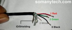
- Check that if you are USB string has more than four wires so 5th one must be a bare/ open conductor. This open wire is generally surrounded to the iv main wire from effectually. This arrangement is called every bit shielding.
- To prevent external dissonance shielding is necessary. The near mutual practice is to ground shielding with the host and external device.
- Shielding is generally avoided in depression quality cheaply made USB cables, which is non in the favor of expert quality USB cords. It is very important for the protection of data. Also for avoiding loss of data and hardware faults.
USB color code:
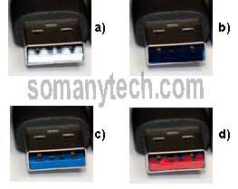
Very few people know that the USB connector has a color lawmaking. This color code is given to the USB on the basis of its standards defined past its organization. The colors are white, blackness, blue, cherry-red/ yellow.
a) White: It was introduced in 1996 (now outdated).It has a very low speed. The version information technology came from is USB 1.XX.
b) Black: It was in the market place since the year 2000. It's under version USB 2.XX. Its speed is up to 480 Mbps.
c) Blueish: It published under the version USB 3.20 in 2008. Its maximum speed is 5 Gbps.
d) Red/Yellow: It is very aforementioned as USB3.XX with an upgraded feature of "sleep and charge". This ways that your device with this characteristic will not cease power supply even if the host device is turned off. This is very helpful for charging the mobile phone according to our convenience.

How To Fix Micro Usb Charger Cable,
Source: https://somanytech.com/usb-wiring-diagram-micro-usb-pinout-guide/
Posted by: brownfrophe.blogspot.com
0 Response to "How To Fix Micro Usb Charger Cable"
Post a Comment